Overall Process Flow — 5 Stages
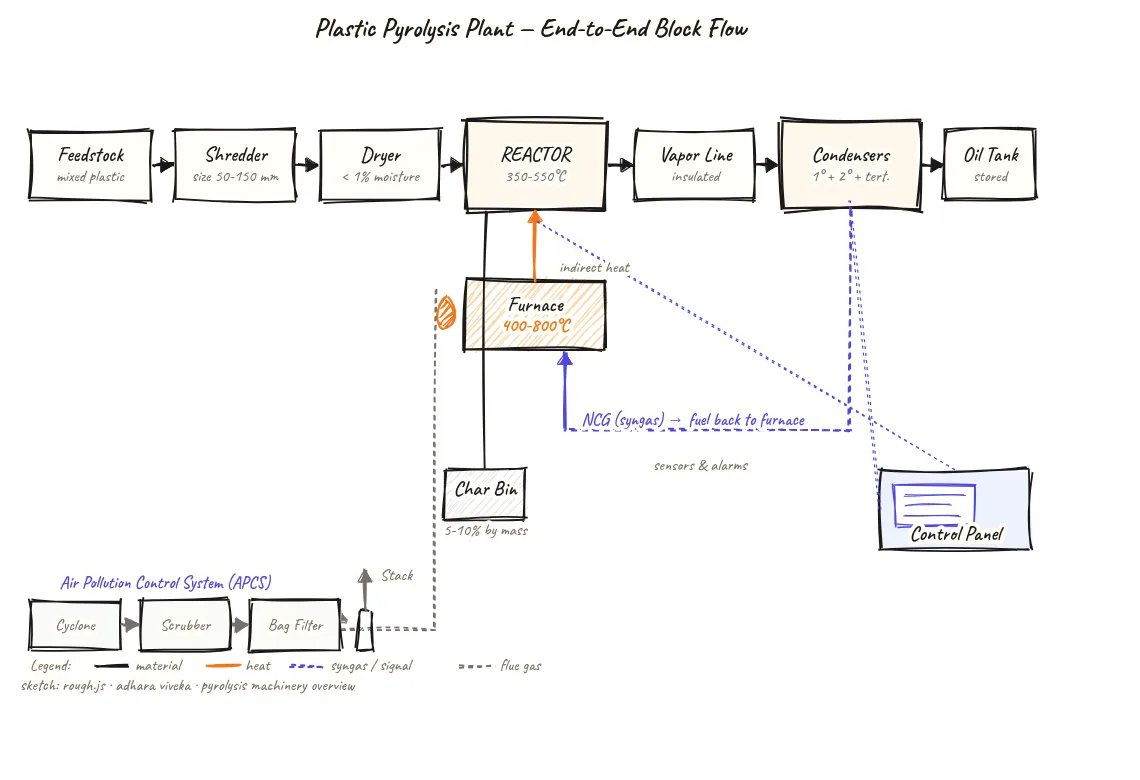
A five-stage block diagram showing the complete sequence of a plastic pyrolysis plant — feedstock preparation, pyrolysis reaction, vapor condensation, product handling, and emission control — giving an instant overview of how every machine in the plant connects.
Beyond definitions
Planning to start a Plastic Pyrolysis business?
Get the full business understanding — capex, regulations, machinery, vendor questions, and risk checks before you commit capital.
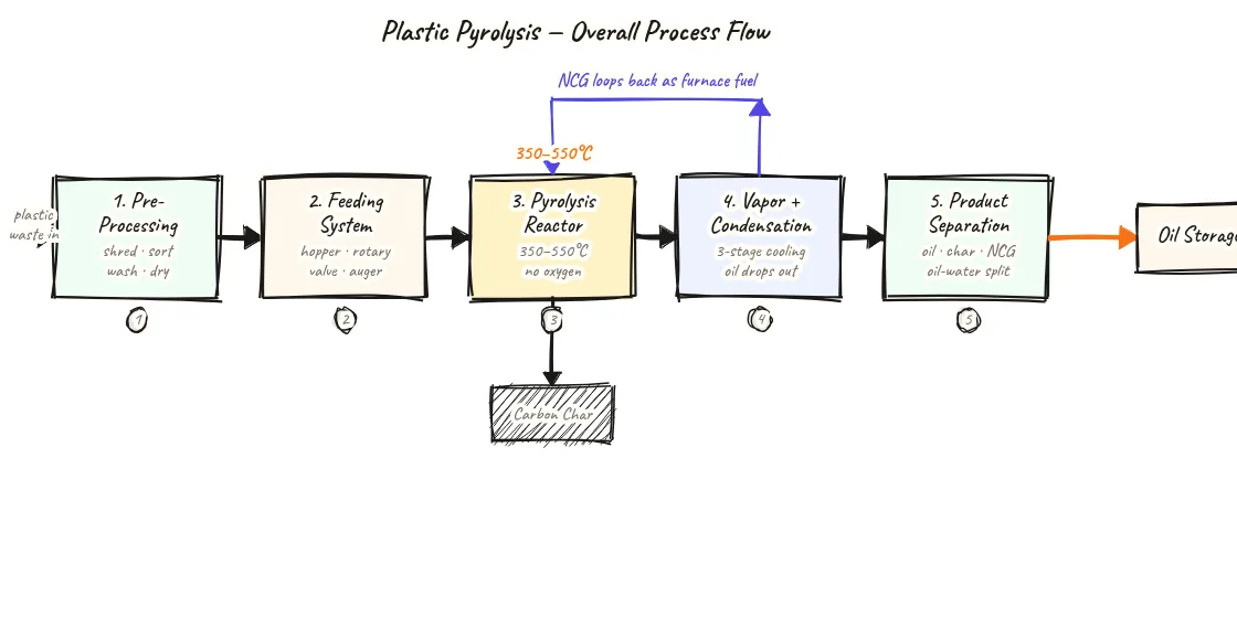
How to read this sketch
This is a left-to-right block flow diagram with five sequentially connected process stages. Read it as follows:
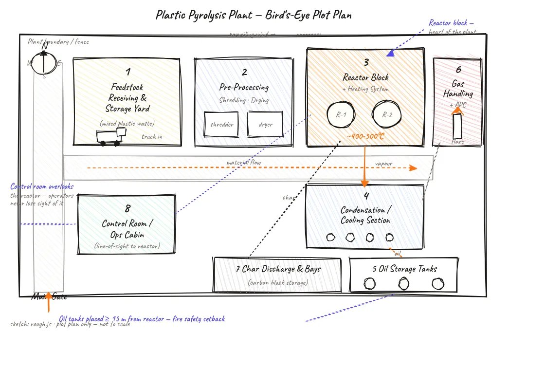
- Five numbered stage blocks: Each represents a group of machines and operations serving a specific function in the process sequence.
- Horizontal arrows (connecting stages): Material flows from left to right through each stage.
- Downward product arrows (at Stages 3 and 4): Show finished products (oil, char) exiting the process sequence downward at the point where they are produced or separated.
- Stage 5 (emission control): This stage receives the furnace flue gas — a parallel output from Stage 2 — not the main product stream. Its purpose is compliance, not product generation.
- Caption: 'Five stages — every pyrolysis plant follows this same sequence.'
About this sketch
Before getting into any individual machine or system detail, a plant-level block diagram provides the map. This five-stage flow shows every pyrolysis plant regardless of size or reactor type — batch, rotary kiln, or fluidized bed. The five stages are the same; the machine choices within each stage differ.
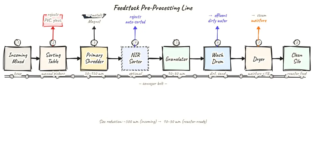
Stage 1 — Feedstock receiving and pre-processing: Incoming plastic waste is received, weighed, sorted, size-reduced (shredded and granulated), washed if needed, and dried. Output is a clean, dry, 10–30 mm feedstock stream ready for the reactor. This stage determines everything downstream.
Stage 2 — Pyrolysis reactor and furnace: Pre-processed plastic feeds into the sealed reactor, heated indirectly by an external furnace to 350–550°C. No oxygen is present — thermal cracking (not combustion) converts polymers into mixed hydrocarbon vapors, syngas, and char. This stage is the core conversion unit.
Stage 3 — Vapor condensation train: Mixed vapors leave the reactor and enter the condenser train, where they cool progressively through two or three stages and condense into liquid pyrolysis oil. Non-condensable gas (NCG) exits the last condenser. Oil is collected at each condenser stage drain. This stage determines oil fractionation and quality.
Stage 4 — Product handling: Three streams are managed: liquid oil stored in the bunded tank yard and dispatched to buyers; char discharged from the reactor after cooling, bagged or binned for sale; NCG routed to the gas holder and furnace burner. This stage is where revenue is measured — quantity and quality of oil and char leaving the plant.
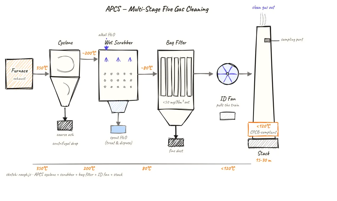
Stage 5 — Emission control (APCS and stack): Furnace flue gases pass through the APCS (cyclone, wet scrubber, bag filter) before exiting through the stack. This stage satisfies statutory compliance requirements and protects the community and operators from harmful emissions.
Key insights
- All pyrolysis plants — batch, rotary kiln, or fluidized bed — follow the same five-stage sequence; only the machines within each stage differ.
- Stage 1 (feedstock preparation) is the most commonly underinvested stage and yet determines oil yield in Stage 3 more than any other variable.
- Stage 3 (vapor condensation) is where revenue is created — the condenser train efficiency directly sets how much of the vapor becomes sellable oil.
- Stage 5 (emission control) is required by law and has no revenue, but a plant without adequate APCS will face consent cancellation and cannot operate.
- The syngas loop between Stage 3 (NCG outlet) and Stage 2 (furnace fuel) is the internal energy link that makes the plant self-sustaining after startup.