Plastic Pyrolysis Plant — Plot Plan
A top-down site layout showing how the eight functional zones of a plastic pyrolysis plant are arranged on a plot, including truck access roads, fire safety setbacks, and control room sightlines.
Beyond definitions
Planning to start a Plastic Pyrolysis business?
Get the full business understanding — capex, regulations, machinery, vendor questions, and risk checks before you commit capital.
How to read this sketch
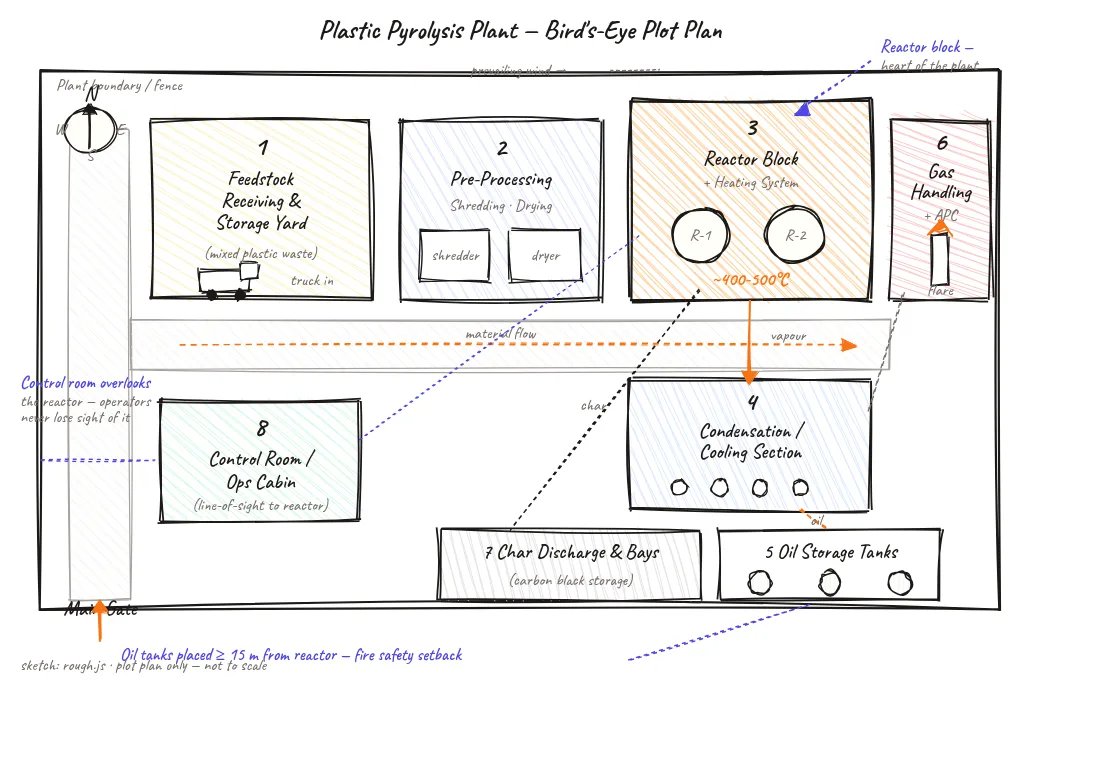
This is a top-down (plan-view) site layout. Read it as follows:
- Numbered zones (1–8): Each box represents a functional area of the plant. Numbers follow the process sequence from feedstock receipt to product dispatch.
- Arrows with direction: Solid arrows show material flow (plastic waste in, oil and char out). Dashed arrows show truck circulation direction.
- Orange highlights: Mark the reactor block — the heat-critical centre of the plant.
- Compass rose (top-right): North indicator. Use with the prevailing wind marker to orient gas handling and flare stack placement.
- Callout lines: Text callouts explain key setbacks and sightline requirements.
About this sketch
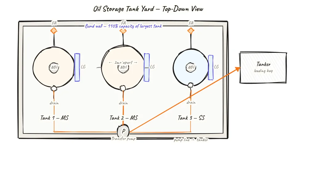
A well-arranged plot plan is one of the first things a licensing authority will look at when reviewing a pyrolysis plant application. This diagram shows a bird's-eye view of a 1040 × 680 m layout with eight numbered functional zones: feedstock receiving and storage, pre-processing (shredding and drying), the reactor block with its external furnace, the condensation and cooling section, oil storage tanks, gas handling with air pollution control and a flare stack, char discharge bays, and the operations control room.
Spatial relationships between zones are not arbitrary. The oil storage tanks are placed at least 15 metres from the reactor block — a fire safety setback required under PESO regulations for flammable liquid storage near a heat source. The control room is positioned to give operators an unobstructed line of sight to the reactor, allowing visual monitoring alongside instrument readings.
Truck movement follows a one-way loop with a single main gate, which keeps incoming feedstock vehicles separate from outgoing product tankers. A prevailing wind indicator on the compass rose helps orient the flare stack and gas handling area downwind of the main working zones — standard practice to keep combustion products away from the site perimeter and worker areas.
For Indian operators setting up a plant in the 5–20 TPD range, a plot of roughly 2,000–5,000 sq m is typical, with the reactor block taking up about 20% of the total footprint. The remaining area is split between feedstock storage (25–30%) and product dispatch (15–20%).
Key insights
- Oil tanks must be at least 15 m from the reactor — a PESO fire-safety setback for flammable liquid storage near a heat source.
- The control room is placed with a direct line of sight to the reactor block so operators can visually confirm instrument readings.
- A one-way truck loop with a single entry/exit keeps feedstock vehicles separate from product dispatch tankers.
- Gas handling and the flare stack are placed downwind of working zones to keep combustion gases away from the site boundary.
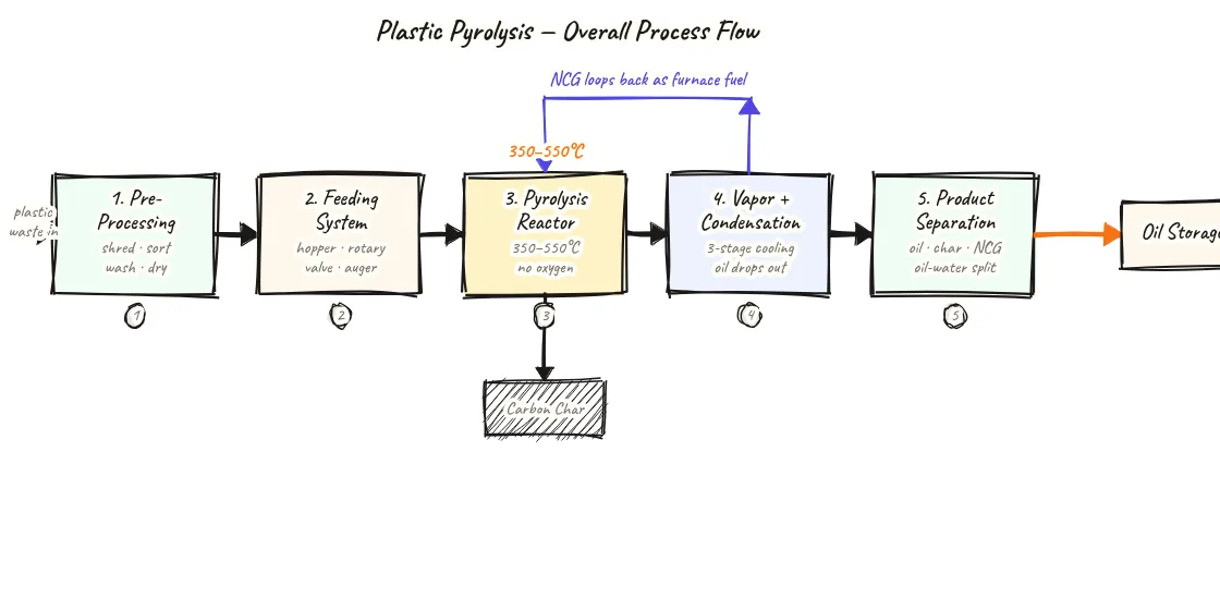
- Eight functional zones follow the process sequence: feedstock → pre-processing → reactor → condensation → oil storage → gas handling → char storage → control.