Control Room + Plant Instrumentation
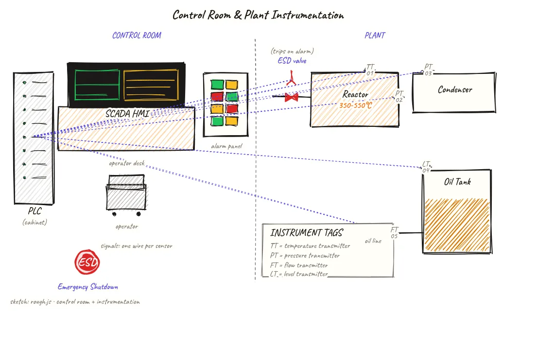
A two-panel diagram showing the control room (PLC, SCADA HMI, alarm panel, ESD button) alongside the plant instrumentation tags (temperature, pressure, flow, level transmitters) — showing how operators monitor and control every critical parameter from one location.
Beyond definitions
Planning to start a Plastic Pyrolysis business?
Get the full business understanding — capex, regulations, machinery, vendor questions, and risk checks before you commit capital.
How to read this sketch
This is a split two-panel diagram. Left panel is the control room; right panel is the plant field. Read them as paired — every instrument tag on the right has a corresponding display or logic loop on the left.
- Control room (left): PLC cabinet (top) → SCADA screen (middle) → alarm panel (side wall) → ESD button (floor-mounted). Vertical cabinet arrangement is typical for a small industrial control room.
- Plant field (right): Process equipment shown schematically (reactor, vapor line, tank). Instrument tags shown as circles with tag numbers. Instrument signal lines (typically 4–20 mA wired pairs) run between transmitters and the PLC.
- Tag codes: TT = Temperature Transmitter, PT = Pressure Transmitter, LT = Level Transmitter, FT = Flow Transmitter. The number after the code is the loop number in the instrument index.
- ESD valve: Shown as a triangle on the vapor line — a pneumatically or electrically actuated valve that closes on ESD signal.
About this sketch
Modern pyrolysis plant control has moved well beyond manual valve operation and temperature dials. This split diagram shows both sides of the control story: the control room where operators work and the plant instrument tags on process equipment that feed data back to that control room.
In the control room, the central piece of equipment is the PLC (Programmable Logic Controller) cabinet — a rack of electronic modules that reads sensor inputs, applies logic (safety interlocks, setpoint alarms, valve sequences), and drives outputs (valve actuators, pump starters, fan variable speed drives). For a 10–30 TPD plant, a mid-range PLC (Siemens S7-300, Allen-Bradley Compact Logix, or similar) is standard. The SCADA HMI (Human-Machine Interface) is the screen that displays a real-time plant mimic — showing reactor temperature, pressures, oil tank levels, and gas holder status in one view. The alarm panel provides audible and visual alerts for deviations. The red ESD (Emergency Shutdown) button triggers a preprogrammed safe-state sequence — closing feed valves, diverting NCG to flare, isolating the reactor.
On the plant side, five instrument tags are shown as examples. TT01 (Temperature Transmitter) on the reactor monitors the most critical process variable. PT02 and PT03 (Pressure Transmitters) monitor reactor pressure and vapor line pressure — the two safety-critical pressure points. LT04 (Level Transmitter) on the oil tank prevents overflow. FT05 (Flow Transmitter) on the NCG line to the furnace monitors fuel consumption. Each transmitter sends a 4–20 mA signal to the PLC, which compares it against setpoints and alarms or acts as needed. The ESD valve on the vapor line closes automatically on an ESD signal, isolating the reactor from the condenser train.
Key insights
- The PLC is the brain of the plant — it enforces safety interlocks that shut down the plant automatically if critical parameters exceed safe limits, without waiting for an operator.
- Reactor temperature (TT01) and pressure (PT02) are the two most critical measurements — both must be in range for safe operation; either going out of range triggers a high-priority alarm.
- An ESD system is mandatory for new plants seeking CPCB and PESO approval — it must be tested periodically and the test records maintained for inspection.
- SCADA HMI gives operators a real-time plant overview, but the PLC logic acts independently of operator action for safety interlocks — the PLC does not wait for a human to press a button if a pressure exceedance is detected.
- A proper instrument index (listing every tag, range, setpoint, and alarm) is a mandatory document for plant commissioning and for any subsequent inspection.